You can see the small amount that stays on the parchment paper. Most transferred nicely onto the copper on the PCB.
A little (some days) later...
the PCB etched and drilled (with the xyz-table as seen on our "Tools" page)
closup of the holes. The drilling was done with the machine under manual control (ie. no steppers,...)
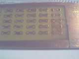
The component side... without the help of the machine, the holes wouldn't look that nice and lined up... :)
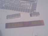
Second try. Different layout. Different display control (multiplexed), so less parts, less holes :)
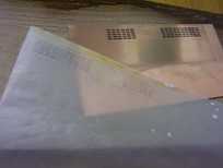
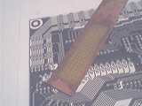
Again using toner transfer, but different paper: a page from an old Reichelt electronics catalog :-))). Something I read about in a german eletronics forum at http://www.mikrocontroller.net/forum
Its just the kind of paper thats used for catalogs. Just cut out a page, print the layout onto it (Yes, it does NOT have to be a white page, any page will do! The catalog print won't interfere!) and iron it onto a pcb. The cool it under running water, carefully peel/rub off the paper and ...
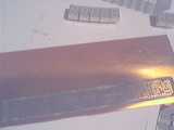
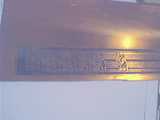
this is what you (might) get. :-)
A little extra work is necessay here because I ironed it too long so some traces have melted to pads (I had to route traces between pads). A sharp knife/scalpel will do the job.
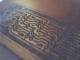
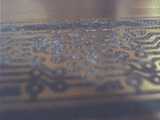
If you moist the board a little, it looks better because the paper fibers are not that obvious when wet.
Here you see a closup where this is obvious. The "white stuff" are paper fibers. As long as they are only on the toner covered parts, they won't be a problem.