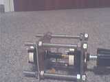
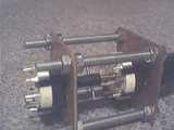
I've built a dual concentric rotary during the last few days...
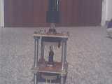
I've tried something new here for the mounting: two pieces of printed circuit board (PCB) with four threaded rods and 16 nuts.
PCB material is really nice to work with. Its flexible, yet sturdy and can be easily manipulated with simple tools.
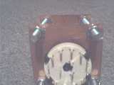
I cut out two 4.5x4.5cm pieces of PCB, layed them on top of each other (so they have all the wholes exactly at the same spots) and drilled four holes for the threaded rods, a 10mm hole for the rotaries and a 3mm hole for the notch of the rotary (to fix it).
I drilled out the plastic axis of the first (outer) rotary and replaced it with a piece of aluminum pipe. Through that runs a 4mm brass rod for the inner knob to the other rotary. There, I drilled a 4.5mm hole into the plastic shaft, stuck the brass rod in. Then I drilled through both the plastic and the brass rod a 1.5mm hole and put a small nail through that hole.
One important advantage of the PCB and threaded rod method is that the distance can be easily adjusted. Also if you want to add a push/pull switch, more "layers" of PCB can be added.
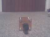
I've drilled a whole into the bottom of the inner rotary. Since there is about 1/2mm play in it now, a switch can be installed that makes use of this play. It might be necessary to add a spring to let the knob come out again after pressed.