After a long time (of thinking and pondering) I have worked on my throttle unit again. I'm gonna use the "bread cutting board" method for friction locks for my throttle levers. I'll probably also redo the board that has the notches for the flaps with a thicker "bread cutting board".
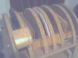
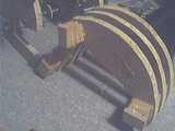
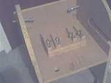
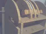
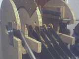
This picture shows the core part of the throttle taken out and pushed over (what you see in front is the bottom)
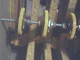
Gear wheels attached to throttle levers
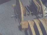
The core part taken apart into two pieces, inner and outer. Flap lever can be seen on the left on the outer part.
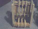
The inner part is only a wooden frame.
The inner wooden frame. Basically three pieces with small rectangle wooden spacers.
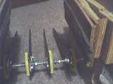
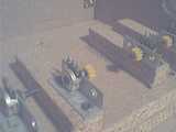
All throttle levers, the flaps and the speed brake levers are mounted to one M6 threaded rod.
There are two metal pieces on each end of the threaded rod to keep it from moving when finally installed in the throttle unit.
the levers.
Pieces of bread cutting board for the friction locks.
Now attached with wood screws (countersinked so they don't disturb throttle lever movemnt)
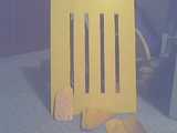
In the back: PVC 3mm (hard foam PVC) that will be the cover for the throttle. You can see the 4 cutouts for the throttle levers.
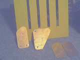
In the front: sidepieces for the throttle switch boxes (the things where the reversers go into, and where the TOGA and AT discon switches are mounted to). They are made from printed circuit board (PCB). Two kinds: for throttle 1 and 4 the smaller ones (4 each, 3 shown) and for throttle 2 and 3 the triangular ones (still rough).
The triangular part is actually 4 screwed together. That way the all are exacly the same.
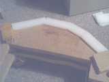
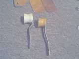
The throttle handle (white) and the reverser handle (not yet painted)
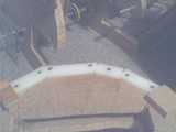
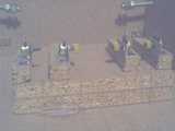
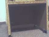
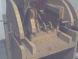
The throttle unit frame. Note the cuts in the sides. They are used to slide in/out the M6 threaded rod with all the levers on it.
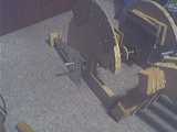
In the middle, the 4 pots with gear wheels (acutally one is missing).
The two M10 threaded rods on each side in the back are used to adjust and hold in place the core part of the throttle. (A little complicated ? ... Yes, but this throttle is a "grown" one. Its gone through several stages of developemnt, ideas, ... )
Pots seen closer
and closer
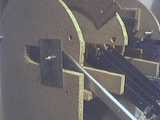
this picture clearly shows the two cuts for the core to slide in.
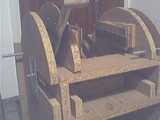
under the throttle...
The thing is pretty heavy due to all the wood, so I added some wheels to it :-)
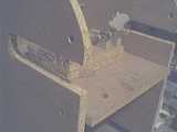
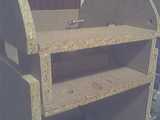
The "slide-in table". One aspect of the "grown" solution. This allows easier access to the pots. The inner core part can rest on this table while it can always be removed by pulling out. (ie. its not screwed on or anything)
The inner core part in the throttle unit frame.
slideing in the outer core part (with the inner core part removed again)
The tricky part is to slightly lift the big gear wheels (attached to the throttle levers) over the small gear wheels and the pots.
Now in-place.
here's how the table fits in
and the inner core part added to it. This makes the throttle unit nearly complete. Just the handles, reversers and throttle switch boxes are missing. (No, the bread cutting board friction locks are not finished yet)