Assembling the PHCC Daughterboards "DOA_7SEG_*"
Intro
The "DOA_7SEG_*" series of Digital Out Type A Daughterboards are used for scanned displays such as seven-segment displays, 14/16 segment displays (a.k.a. starburst displays) and also individual LEDs.
The boards "DOA_7SEG_2803", "DOA_7SEG_2981", and "DOA_7SEG" (Rev.1) are capable to drive up to 32 seven-segment displays, 16 fourteen/sixteen segment displays, or 256 LEDs, or any combination thereof.
All segments can be controlled individually. This allows flexible wiring and also displaying of non-standard characters.
Variants
The differences between those three boards are:
- DOA_7SEG_2803 is for common cathode displays
- DOA_7SEG_2981 is for common anode displays
- DOA_7SEG (Rev.1) can drive both common anode and cathode displays, based on jumper/chip selection.
The resistor arrays RN1,RN2 (package: DIL-16) might not be easy to find in some areas. It is also possible to use 8 single resistors instead. In this case you could skip the step with the RN1/RN2 socket. Or, you could use a machined (turned) DIL-16 socket for the single resistors. Either just plug the resistors in the socket contacts or solder them to it.
How to connect stuff...
DOA bus to CON1, +5V and GND to CON5.
CON3 and CON4 go to the segments, CON3 is responsible for displays 1-16 (Channel A), CON4 for displays 17-32 (Channel B). The display commons (anode or cathode, depending on board) connect to CON2. There are only sixteen commons. Each serves two displays, one of Channel A, the other of Channel B.
For more info see docs.
Assembly
First start with the smaller components and work your way up to the bigger ones like sockets and connectors. This helps at places where the bigger stuff might get in the way of soldering smaller parts.
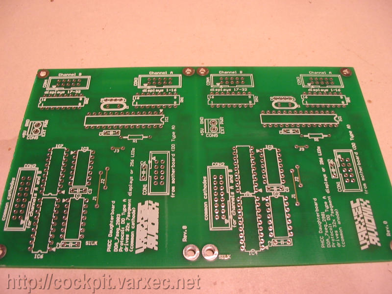 |
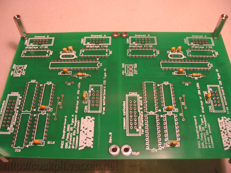
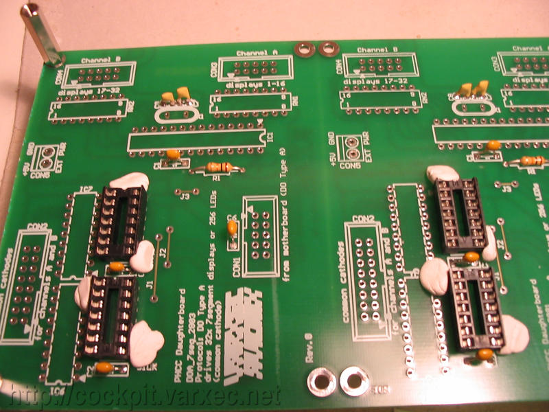
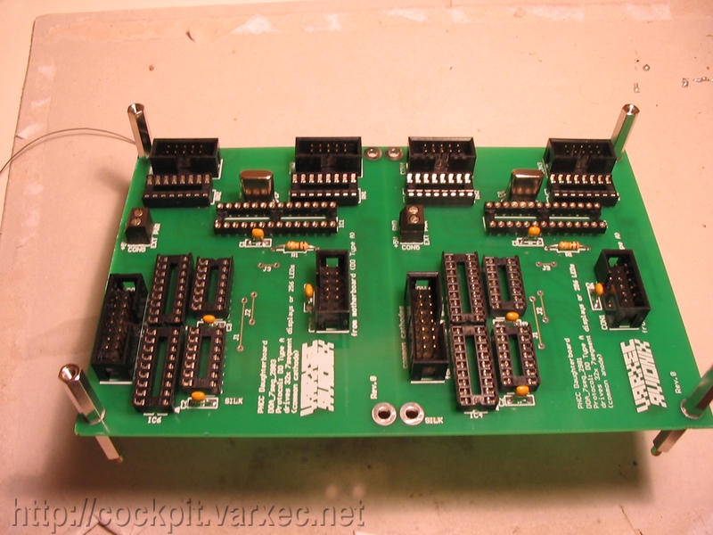
We will make a combined board that has both a DOA_7seg_2803 (left) and a DOA_7seg_2981 (right). We'll build both boards at the same time, so nearly everything needs to be done twice. |
 |
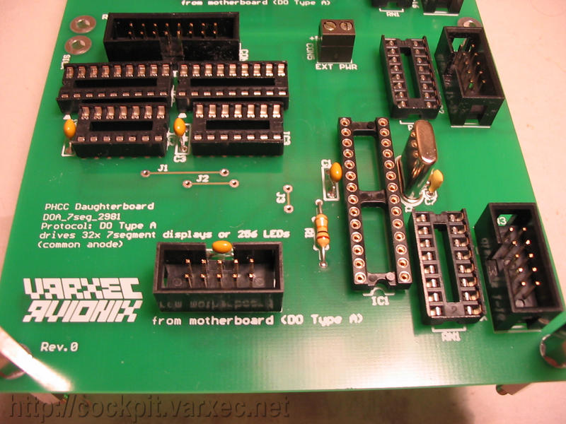
Closeup of the common anode bare board. |
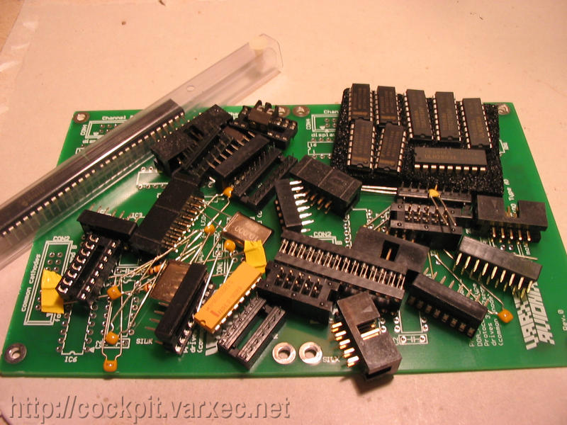 |
All the needed parts piled up on the bare board. (These are parts for both halves). |
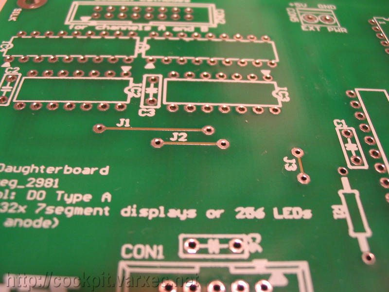 |
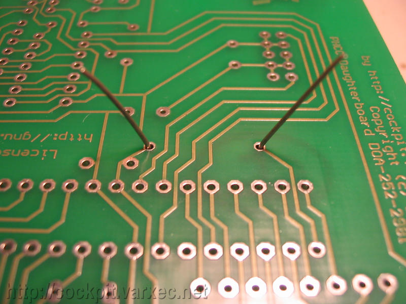
If you don't have a double-sided board, start with the jumper wires J1-J3. |
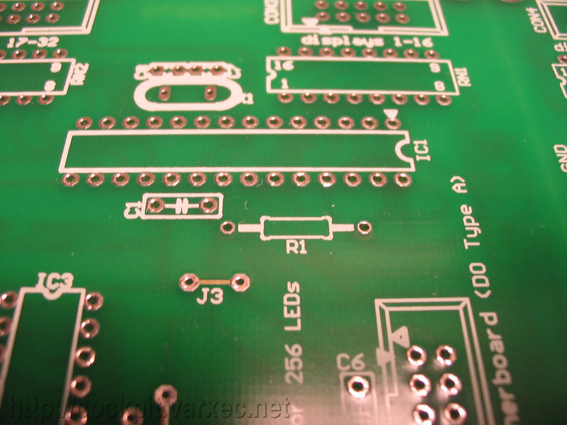 |
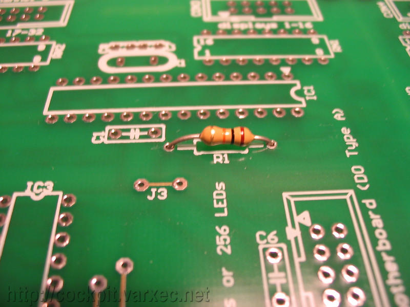
First start off with the resistor, R1. |
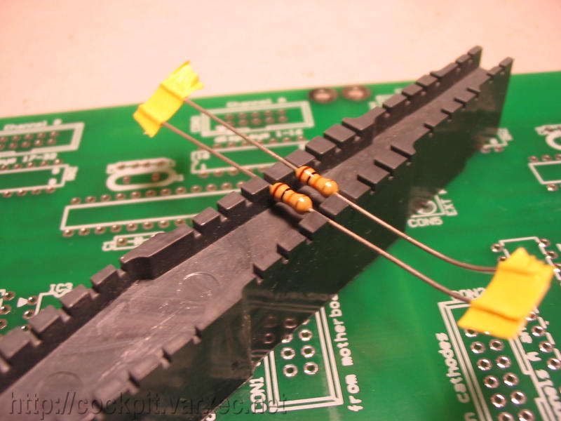 |
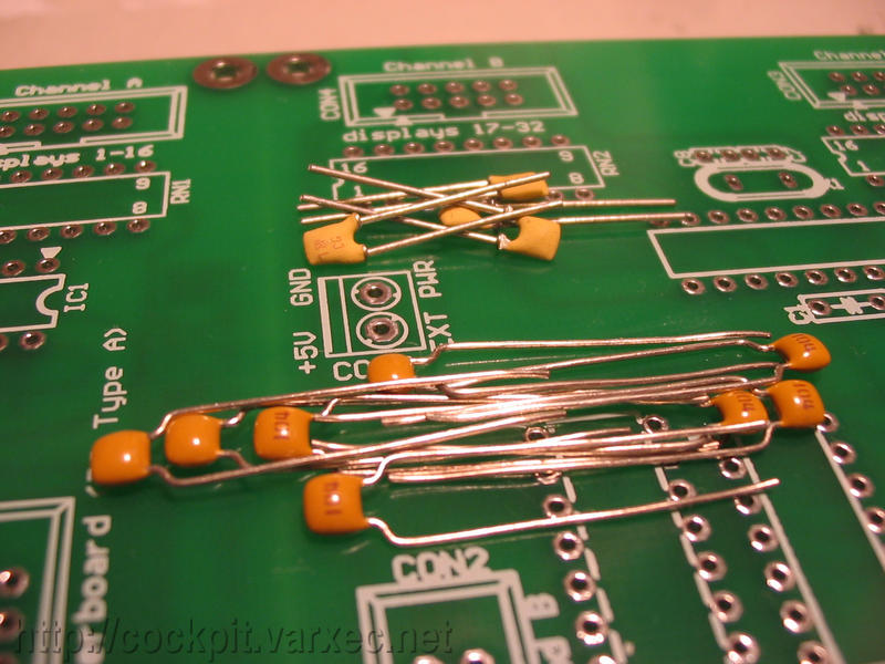
Bend the leads of resistor R1 to the appropriate size. (Two of them in my case, as I build two boards at once). Using a tool like this makes it easier but is not necessary. |
 |
Put them in the correct holes. |
 |
Bend the leads outward so the resistor doesn't fall out when the board is turned upside-down for soldering. |
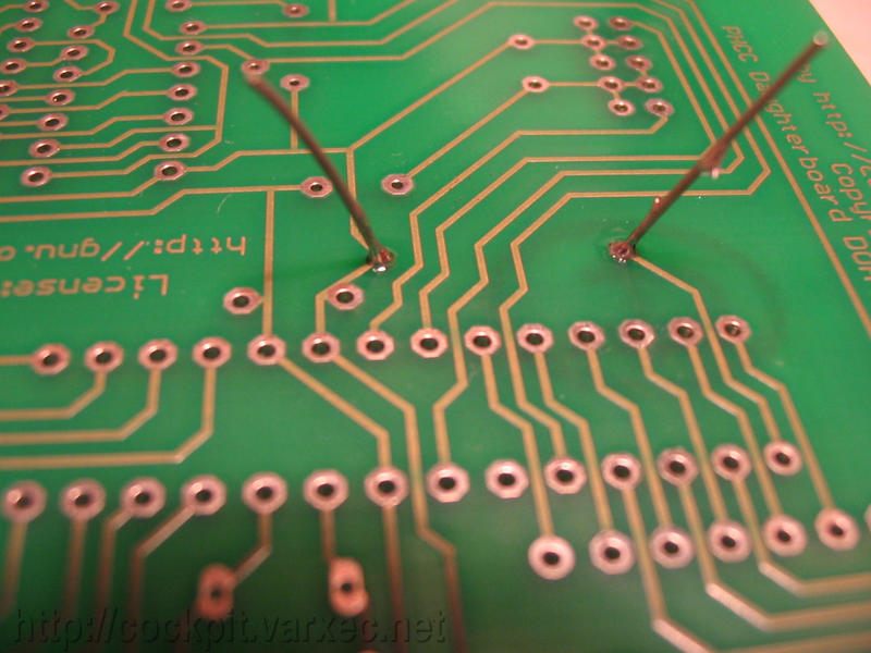 |
Solder. |
 |
Clipping off excess lead length. |
 |
Next are the ceramic capacitors. * DOA_7SEG_2803/DOA_7SEG_2981 Rev.0: C1-C3, C6-C8 * DOA_7SEG_2803/DOA_7SEG_2981 Rev.0B: C1-C6 * DOA_7SEG Rev.1: C1-C6 |
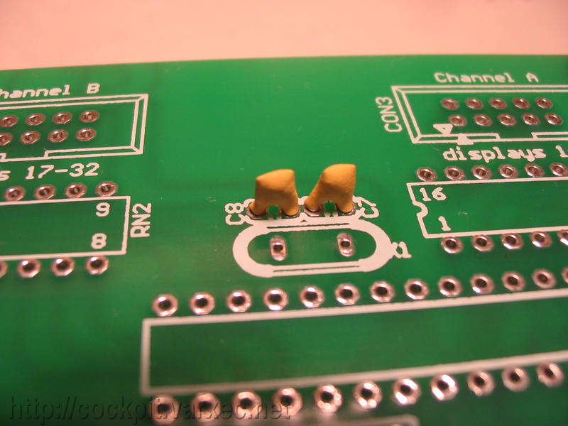 |
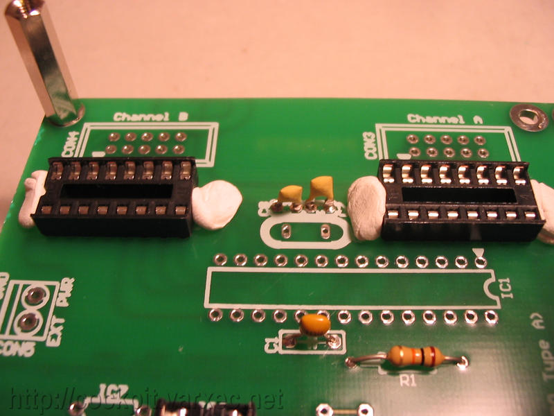
The crystal oscillator caps in detail C7,C8(Rev.0) / C2,C3(Rev.0B, Rev.1). |
 |
Solder. |
 |
Same with the other ceramic caps, C1-C3,C6(Rev.0) / C1,C4-6(Rev.0B, Rev.1) |
 |
Closeup shot. |
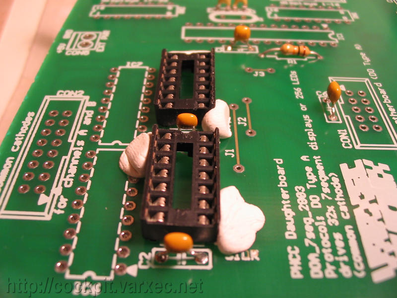 |
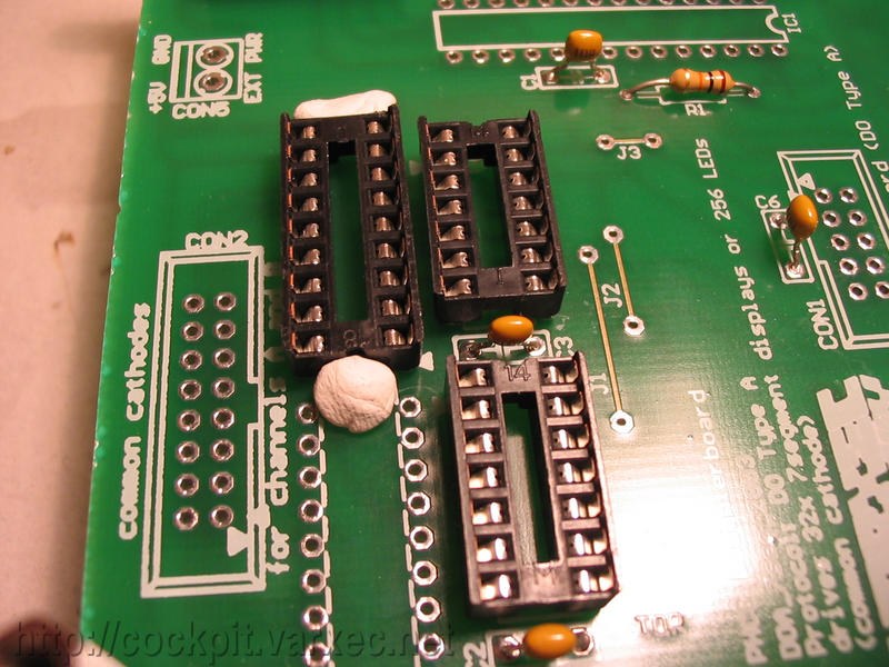
Now move to the IC sockets. Start eg with those for IC2-IC3. Using removable adhesive putty (eg. Plasti-tak(R)) helps to hold the parts for soldering. |
 |
I did both boards at once. |
 |
Now solder them. |
 |
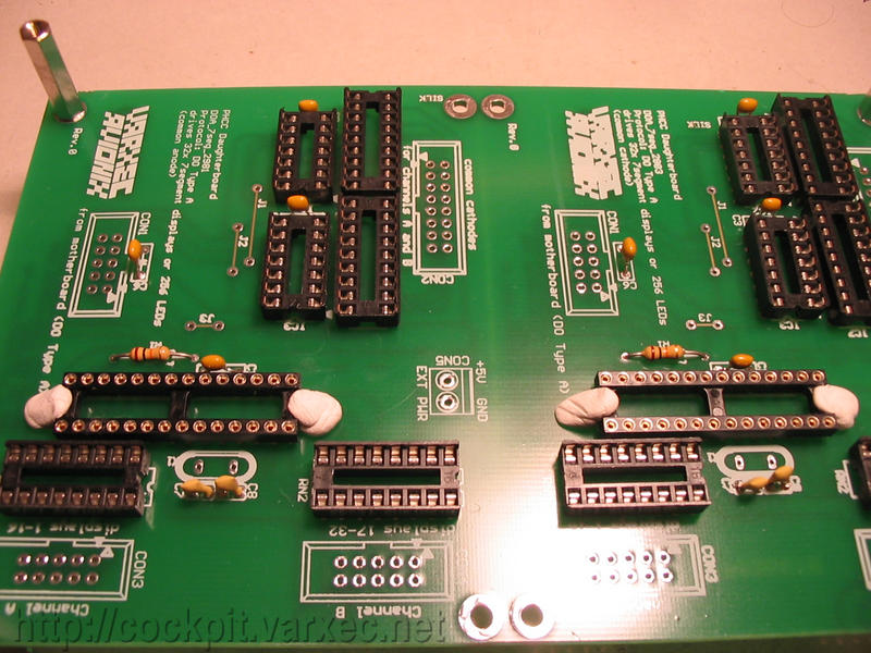
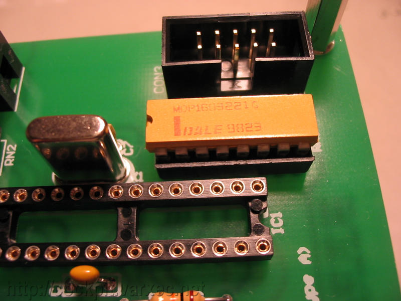
Same for the Resistor array RN1-RN2 sockets. If you don't use DIL resistor arrays, check the Variants section. |
 |
Next add the sockets for the commons driver chip, IC6-IC7. |
 |
The second one. |
 |
And now the socket for the PIC, IC1. I'm using precision/turned sockets, but cheaper standard type is also ok. |
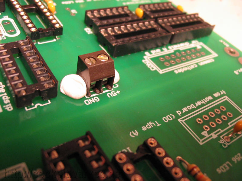 |
Move to CON5, the external power screw clamp terminal. |
 |
Not shown here is the electrolytic cap, C7, as it has been added in newer board revisions. It sits next to the Ext. Pwr. screw clamp terminal and is included with revisons beginning * DOA_7SEG_2803/DOA_7SEG_2981 Rev.0B * DOA_7SEG Rev.1 |
|
|
Only in Rev.1: JP1, the jumper to select between common anode/cathode. |
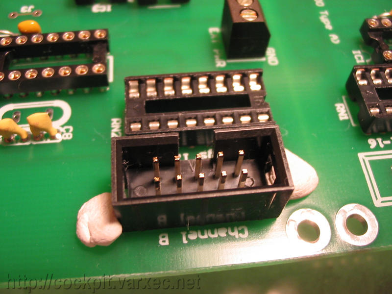 |
Next is CON1(DOA connector), CON3 and CON4 (segments channels A and B). Solder. |
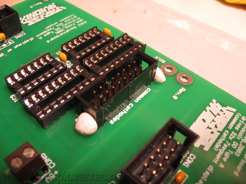 |
Then do the same with the commons connector, CON2. |
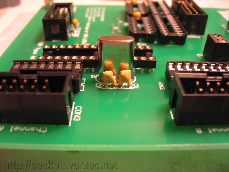 |
And the last part, X1, the crystal oscillator. |
 |
The finished boards. |
 |
Closeup of the finished common anode board. |
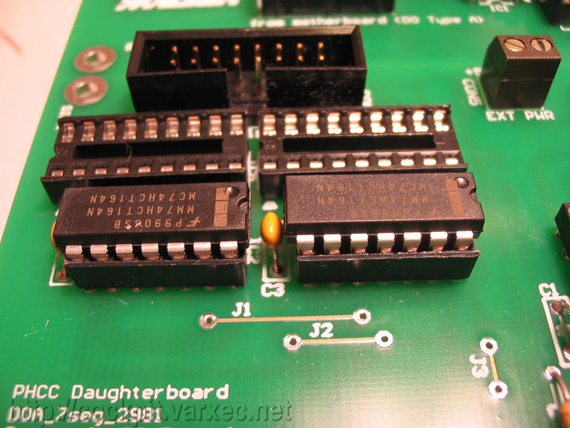 |
Adding the ICs... the shift registers (74HCT164). |
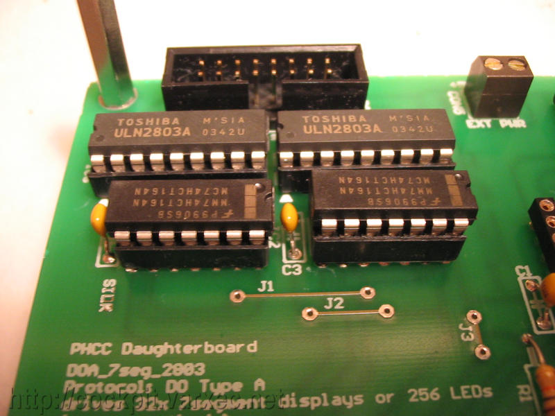 |
and the commons driver chip. Seen here is the ULN2803 for common cathode displays. If you have a Rev.1 board, make sure you set the JP1 jumper correct, as indicated on the silk screen. |
 |
The resistor arrays for the segment channels A and B. Again, you could also use eight single resistors. |
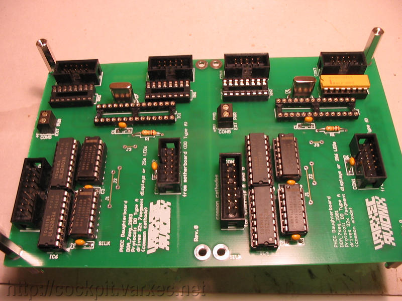 |
The finished board with nearly everything. The PICs and 3 resistor arrays still missing. |
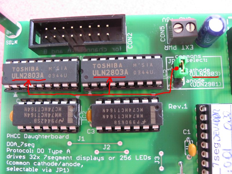 |
This closeup shows the relationship of driver chip, jumper setting, and whether common anode or common cathode drivers are used. Note that both driver chips have to be the same. No mixture of ULN2803 and UDN2981 possible! |
Thats it :)