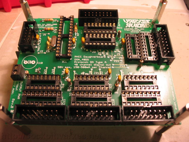
Assembling the PHCC Daughterboard "DOA_40DO"
Intro
The "DOA_40DO" Digital Out Type A Daughterboard can be used for a wide variety of digital output tasks. Each of the 40 channels can be controlled individually and are rated 50V at 125mA continous.
The outputs are current sinks, aka low side drivers. This means that devices to be controlled via the 40DO board will need to be connected between the positive power supply (labeled "+Vout") and one of the 40DO "outputs" on the device's negative side.
A few examples of devices that can be controlled with the DOA_40DO board are:
- relays
- solenoids
- small DC motors
- incandescent lamps
- LEDs
- 7segment displays
- 14/16 segment displays
The main difference of using the DOA_40DO instead of the DOA_7seg for LEDS/segmented displays is that using the 40DO, full brightness can be attained as no multiplexing is done, but the costs are higher since one 40DO board could drive up to 40 segments or LEDs while the DOA_7seg board can drive up to 256 segments/LEDs.
How to connect stuff...
DOA bus to CON1, output power (+Vout, 3-50V) and output power GND to CON2.
CON3 to CON7 carry 40 pairs of output "sink" and +Vout.
E.g.: Connecting a relay
Choose one of the 40 pairs, connect one side of the relay coil to one of the two wires, and the other side to the other wire of the pair.
E.g.: Connecting a LED
Choose one of the 40 pairs, take a LED and a current limiting resistor, wire the LED and resistor in series (doesn't matter if the resistor is connected to anode or cathode of the LED). Then connect the LED anode to the +Vout wire of the pair, and the LED cathode to the "sink" output of the pair.
E.g.: Connecting an incandescent lamp
Choose one of the 40 pairs, connect the lamp between the two wires of the pair. Polarity doesn't matter. Just make sure that +Vout is within the operating voltage of the lamp.
Assembly
If you don't have a double-sided board, start with the jumper bridges. Otherwise you can jump right in with the smaller components and work your way up to the bigger ones like sockets and connectors. This helps at places where the bigger stuff might get in the way of soldering smaller parts.
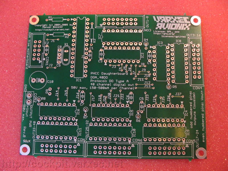 |
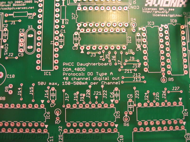
This is the bare board. Notice CON2, the screw clamp for +Vout. It is necessary to provide power via this screw clamp for the outputs since they are not supplied by the 5V logic supply. |
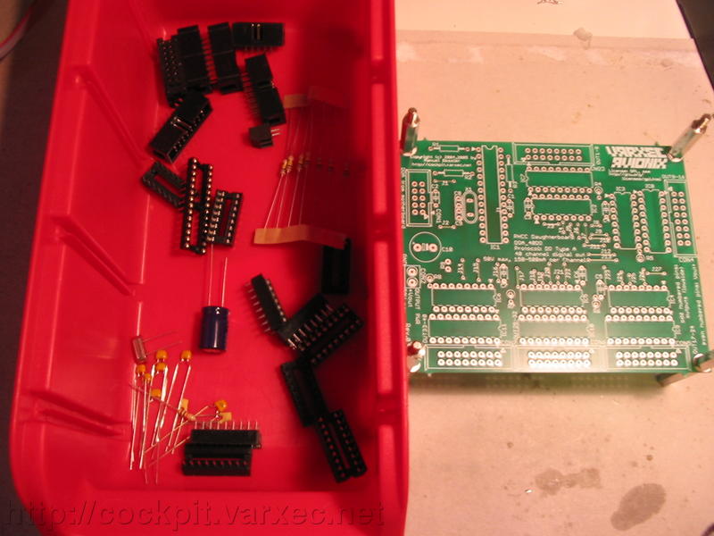 |
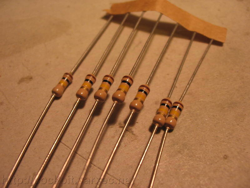
The parts needed (except ICs). |
 |
All parts piled up, again without ICs. |
 |
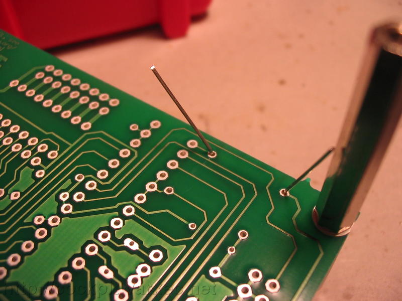
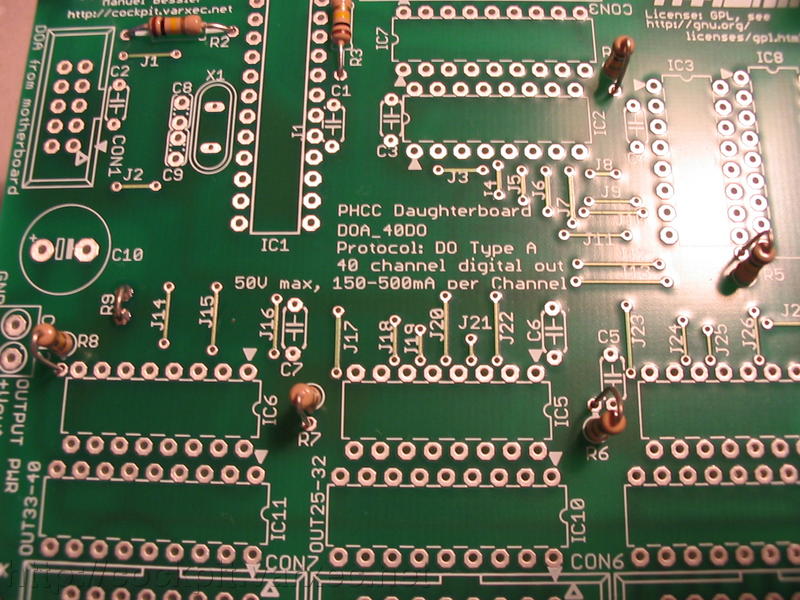
For you folks who don't have a double layer board, start now with the jumper bridges, J1-J27. |
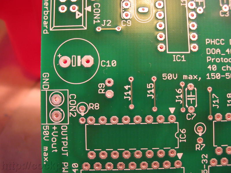 |
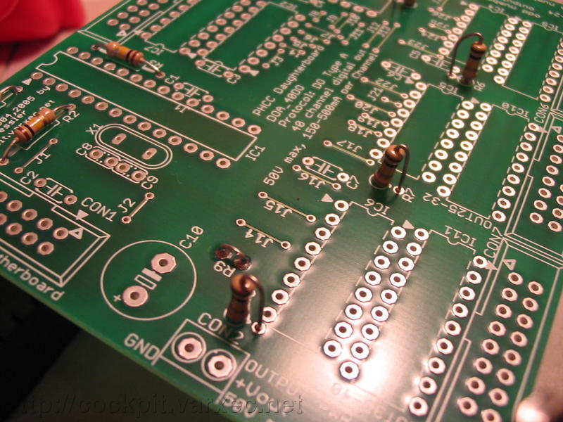
Notice R9. This is really not a resistor, but another jumper wire. Also called a 0R resistor. We'll get to R9 in just a minute. |
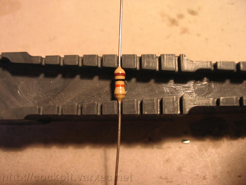 |
But first we need to get R1, the 10k resistor. Bend it (manually or with a helper tool like this). |
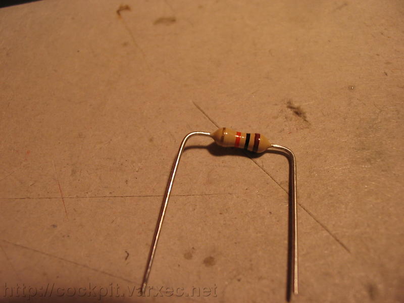 |
After it's bent... |
 |
Insert it into its designated place... |
 |
Bend the wires a bit so the resistor can't fall out when we try to solder it. |
 |
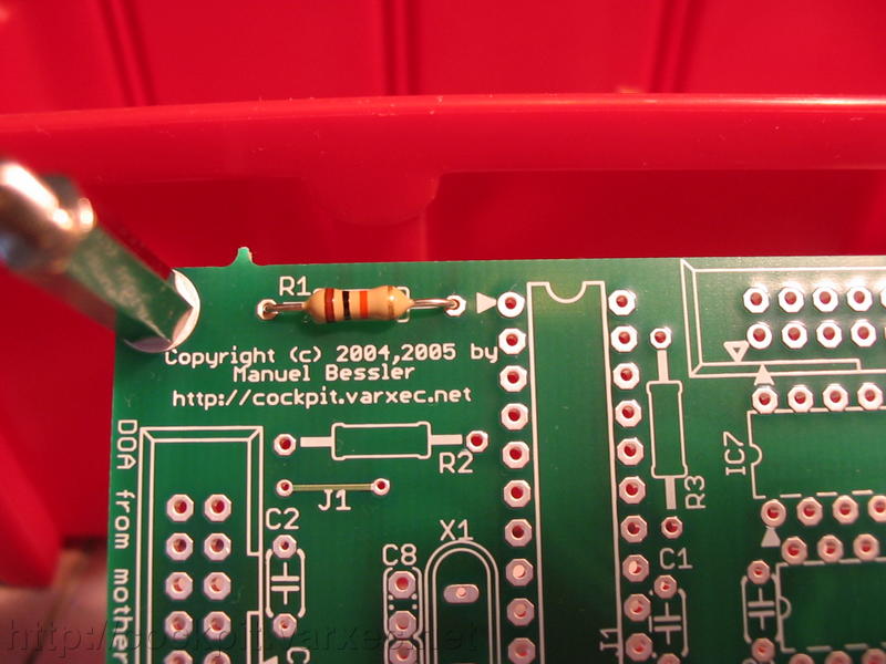
Now solder it. |
 |
Clip off the remaining lead piece and KEEP one of the pieces... |
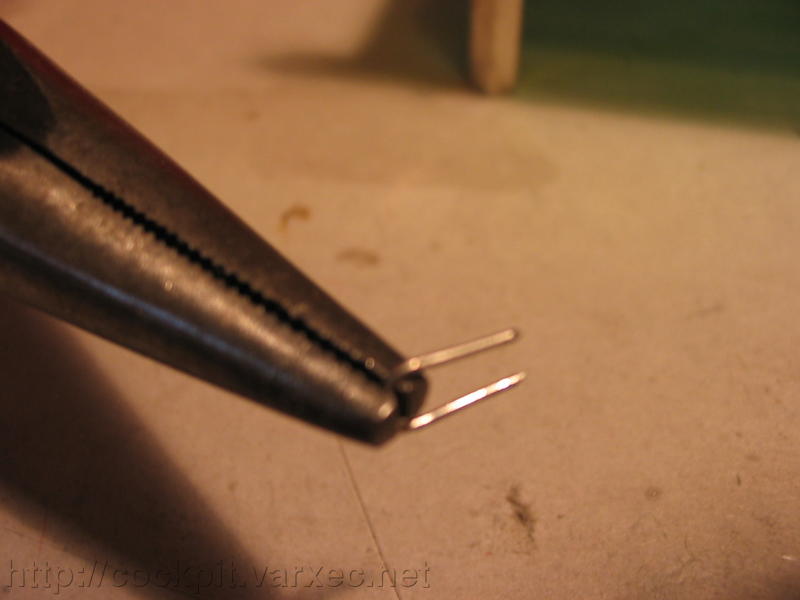 |
...because we are gonna use it for our 0R resistor, R9. Bend it like this... |
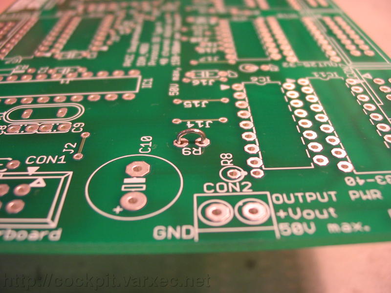 |
and put it into the holes for R9 like this and solder. |
 |
The next kind of resistors are the 100k types used for R2-R8. |
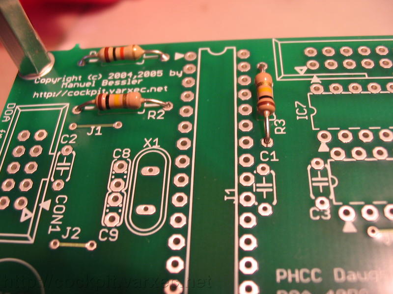 |
Solder two of them (R2,R3) horizontally, just like R1. |
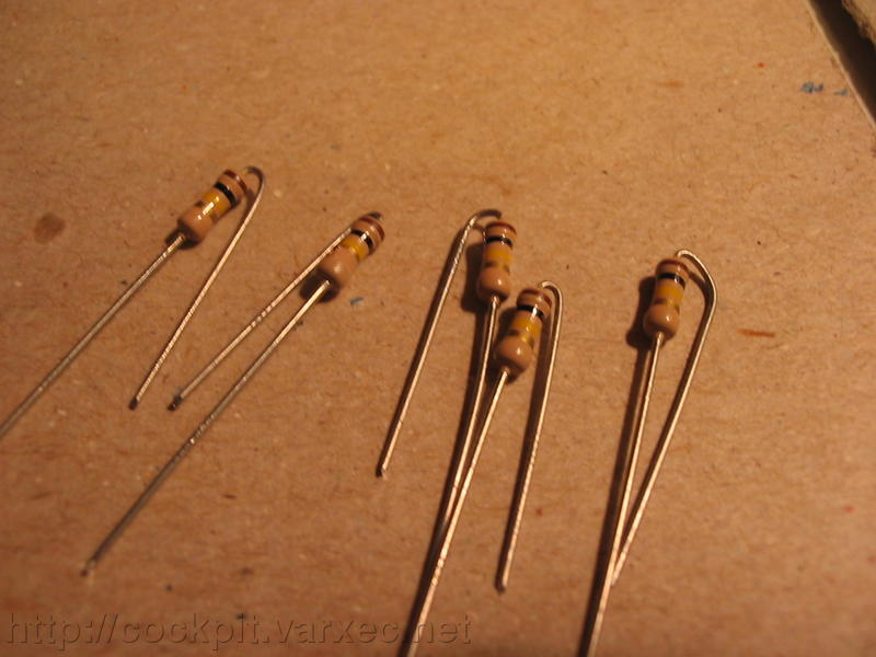 |
And bend the remaining five like this. These will sit vertically. |
 |
Like this. (R4-R8). |
 |
Or like this. |
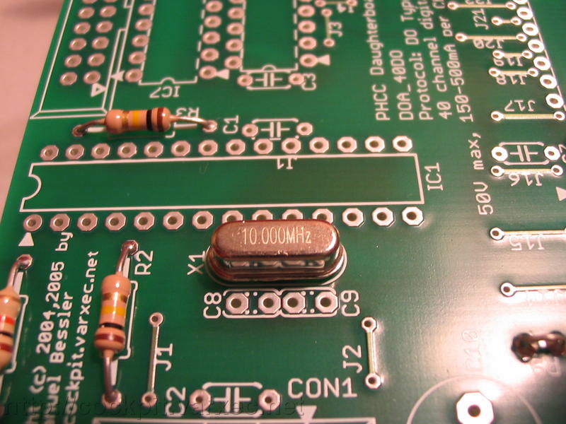 |
Next in line is X1, the quarz crystal oscillator. I'm using low profile types here. |
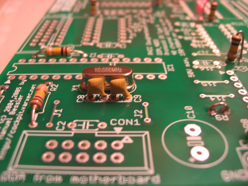 |
Continue with C8 and C9, the compagnion capacitors for X1. |
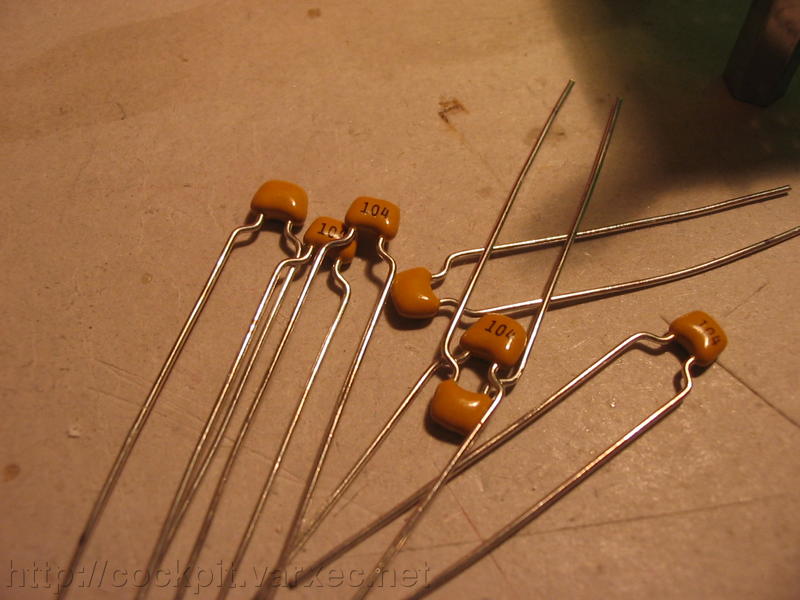 |
Each logic IC gets its own ceramic blocking capacitor with 100nF. Caps with Z5U or X7R dielectric work well. |
 |
There are seven 100nF ceramic capacitors. One for IC1 (C1), one for CON1 (C2), |
 |
and one for each of IC2-IC6 (C3-C7). |
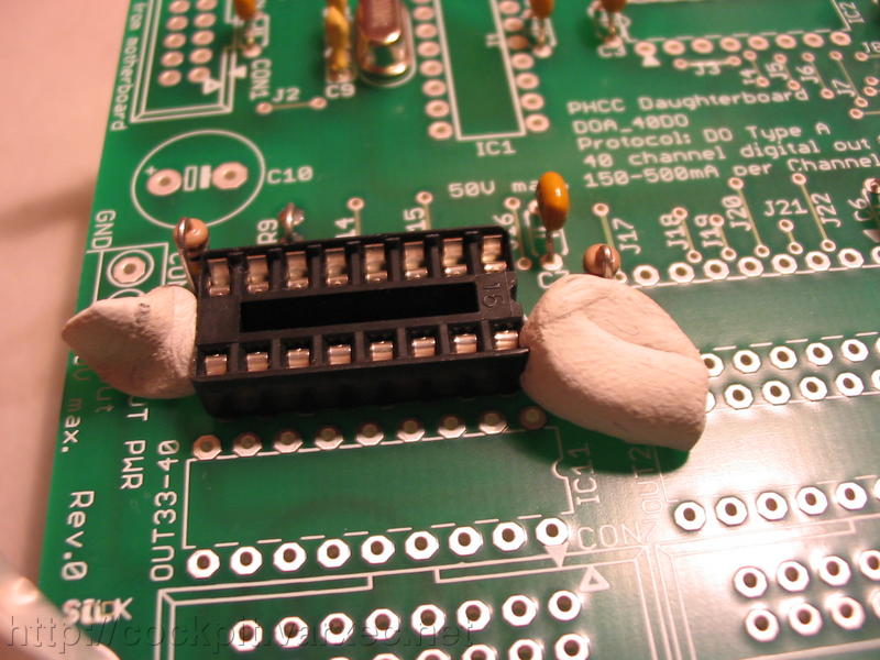 |
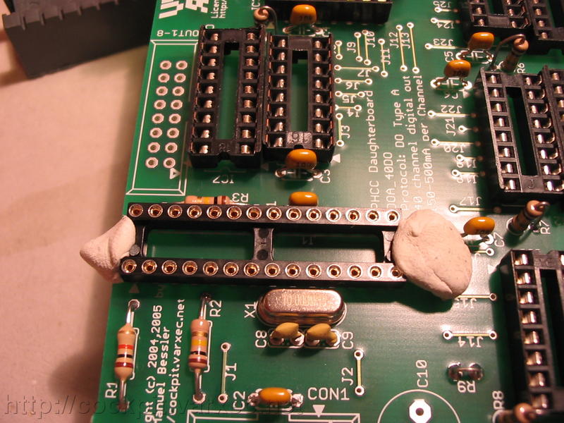
Moving on to the IC sockets... starting with the smallest ones, IC2-IC6. I first fix them in place with two pieces of removable adhesive putty (sticky tack,...) |
 |
and solder just two opposing corner pins at first. |
 |
Then take the next IC socket, do the same. |
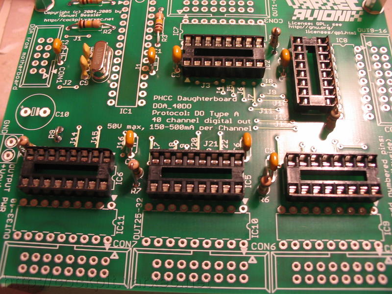 |
Now I have five sockets in place, soldered on two corners. |
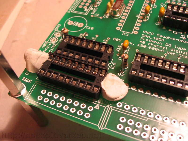 |
Repeat with the next IC socket type. (IC7-IC11). |
 |
When they are also in place, |
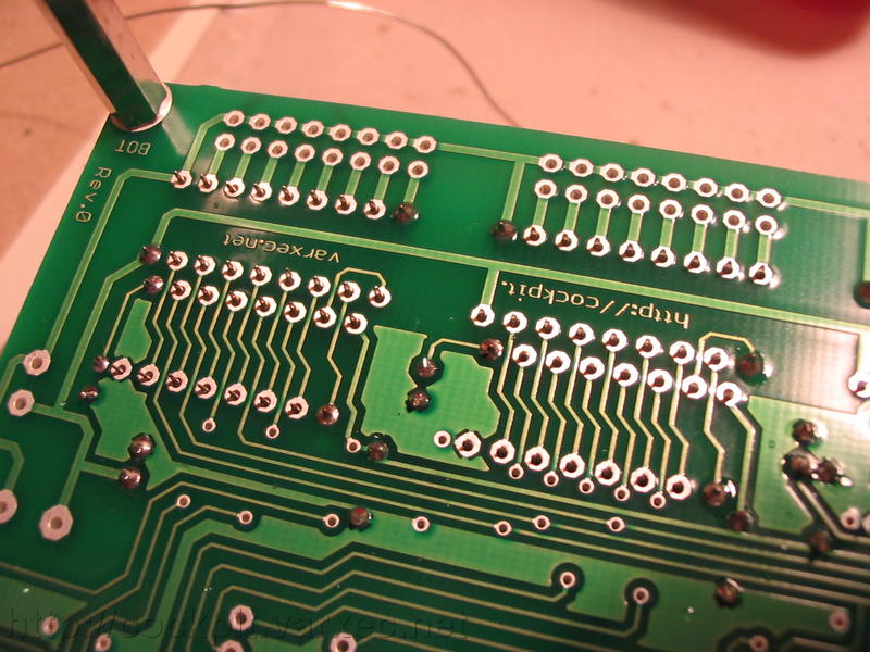 |
solder the rest of the IC pins. |
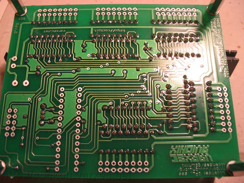 |
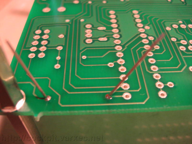
The bottom side of the board should now look similar to this. |
 |
The last IC socket is IC1, for the PIC microcontroller. |
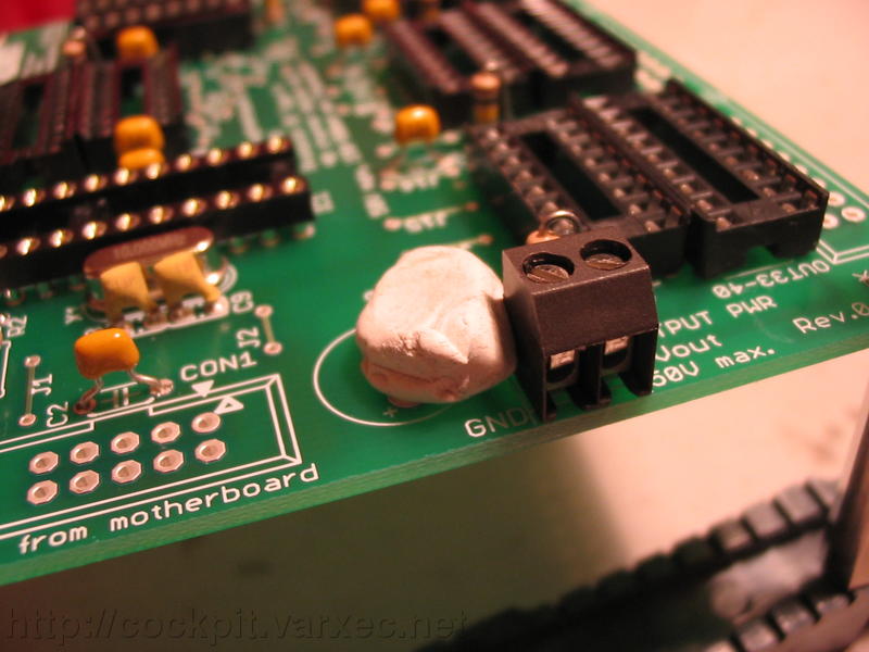 |
Move on to CON2. Again, I used removable adhesive putty to keep the part from falling out before soldering. |
 |
CON1 is next. |
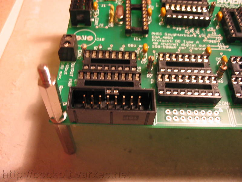 |
Continue with CON3-CON7. |
 |
It should now look like this. |
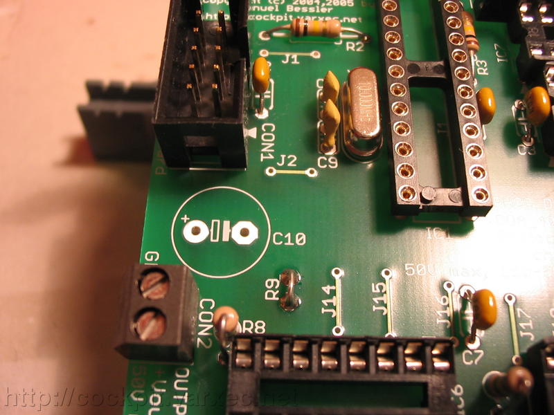 |
Our last part is C10, an electrolytic capacitor. |
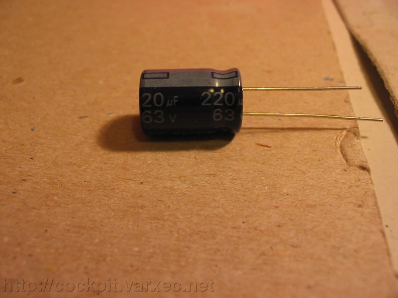 |
Its a radial 220uF cap with a voltage rating of at least 63V. Note the white bar on one side of the capacitor. Its the negative lead, thats why its maked with '-'. |
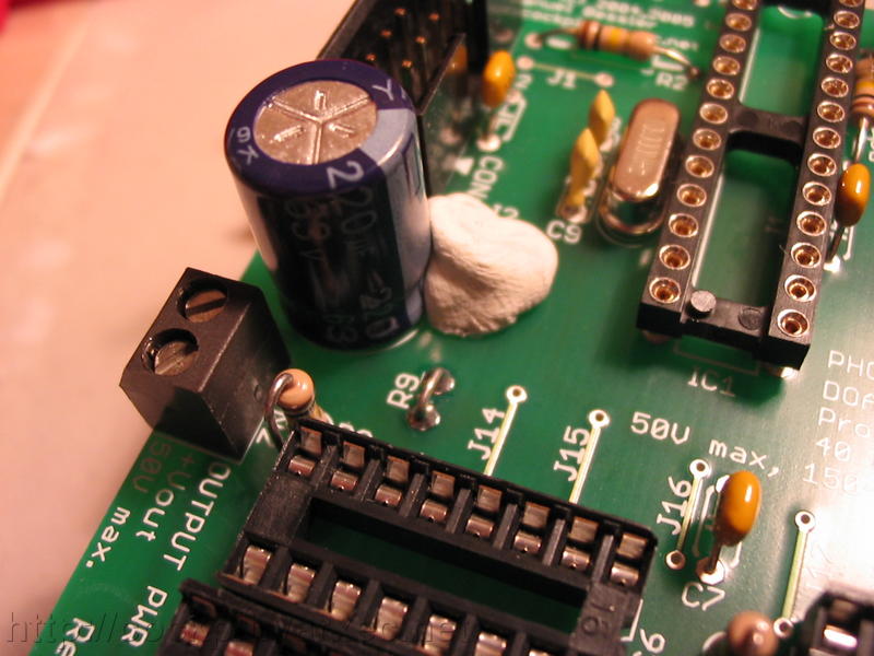 |
Put C10 in place, making sure the polarity is correct. Wrong polarity can lead to an explosion of the cap! |
 |
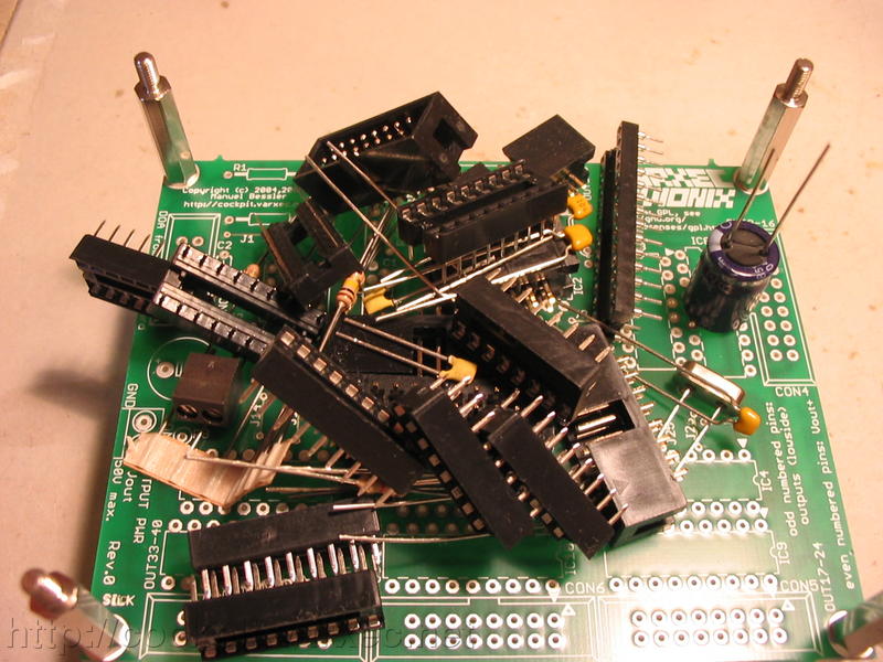
Thats it. All thats missing now are the ICs. |
Thats it :)