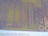
This gallery shows the 48 channel 7 segment display driver board. Its connected to the PHCC motherboard via the Digital Type A bus. The board is controlled by a PIC 16F877 or similar, or a 40 pin chip from the 18F series. The board is only half Eurosize big (80x100mm), so I put two controllers onto one Euro size PCB as seen in the picture.
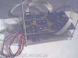
This prototype is for Stephens Radiostack and GPS unit. We used the toner transfer method again. This time even the component side print was ok since I avoided moving the board while the plastic spray was drying.
The displays are driven by 8 bit values and not by BCD, so you can have any segment (including the decimal point) light up in any combination.
Of course, you can hook up LEDs instead of 7 Segment displays, no problem.
You can drive 96 7 segment displays (or 96*8=768 LEDs) for as little as 25 Euros!!! (assuming no sockets for the ICs and resistor arrays, and of course you need the PHCC motherboard)
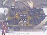
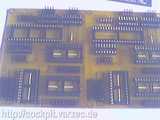
Component side. Holes for the pinheaders are 1.0mm and others are 0.8mm. Drilled using our XYZ machine, under manual control (ie. no steppers/computer control).
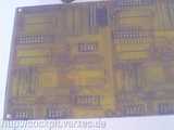
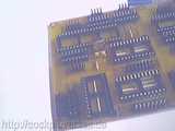
The big 40 pin IC is the PIC, the 16 pin DIL sockets are for the resistor arrays.
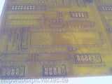
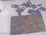
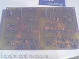
Solder side. Lots'o holes...
as you can see here. Using the XYZ table really helps. We didn't break any drills and the holes can be drilled pretty exact.
And closer. The 1mm holes for the pinheaders don't leave too much copper for soldering, just barely enough.
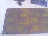
With all sockets and pinheaders soldered in. Caps and oscialltors still missing.
Solder side.
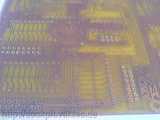
Resistors, oscillators and some caps added. I realized that the caps I used in the layout were to small. I didn't have enough of those tiny (blue) caps around, so only one side was done (with one cap missing).
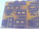
Ready for the ICs...
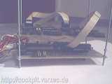
The "avionics stack". The bottom board is the PHCC motherboard. More boards to be added to the top :-)